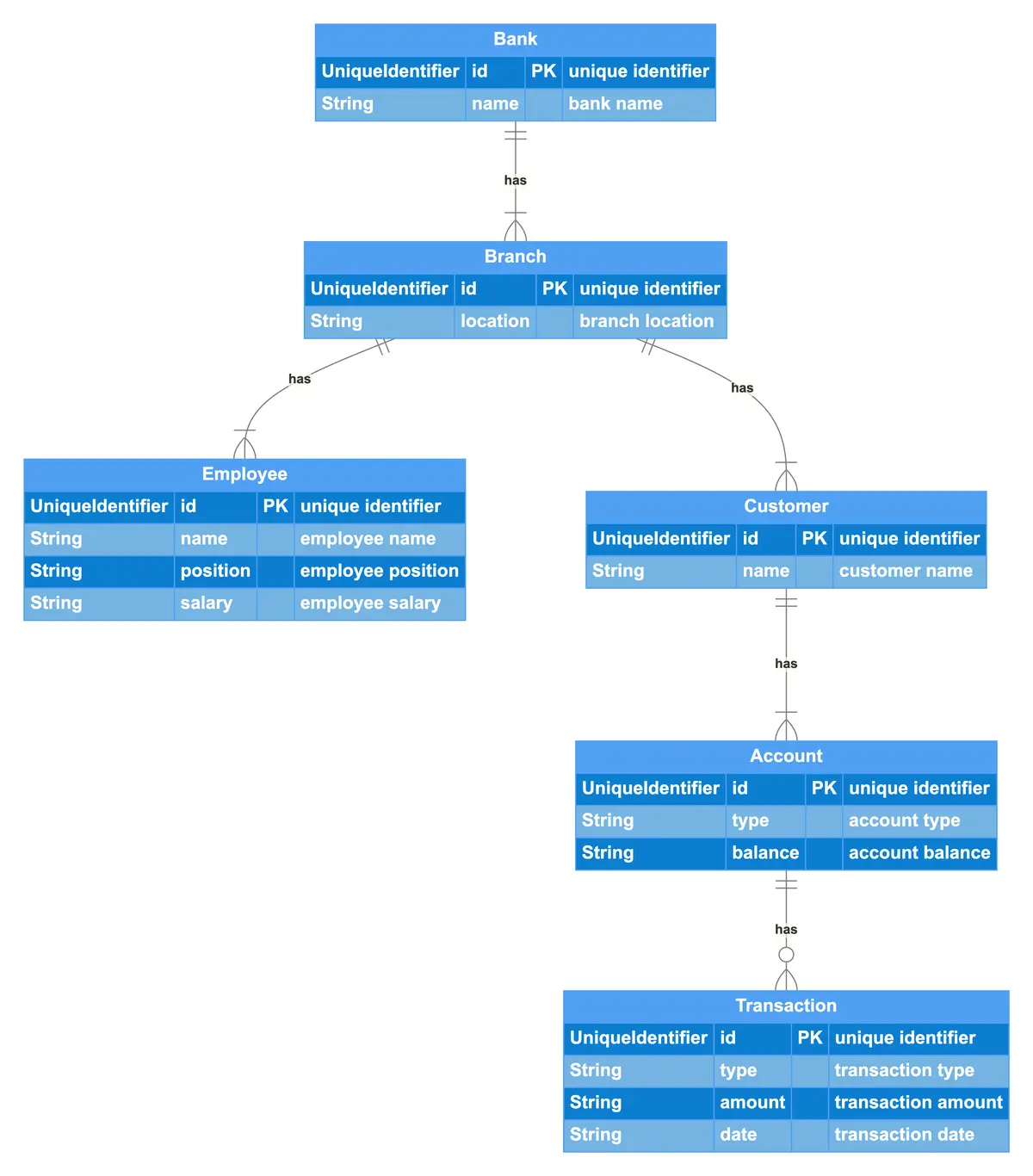
This ER diagram depicts a Banking System involving Banks, Branches, Employees, Customers, Accounts, and Transactions. Banks have branches, with each branch located at a specific location. Branches have employees, customers, and accounts associated with them. Employees are staff members of branches, with each employee having a name, position, and salary. Customers have accounts, with each customer linked to one or more accounts. Accounts hold transactions, indicating the movement of funds within the banking system. The relationships between these entities illustrate how banks manage branches, which in turn serve customers through employees handling accounts and transactions.

UniqueIdentifier id PK "unique identifier"
String name "bank name"
UniqueIdentifier id PK "unique identifier"
String location "branch location"
UniqueIdentifier id PK "unique identifier"
String name "employee name"
String position "employee position"
String salary "employee salary"
UniqueIdentifier id PK "unique identifier"
String name "customer name"
UniqueIdentifier id PK "unique identifier"
String type "account type"
String balance "account balance"
Transaction
UniqueIdentifier id PK "unique identifier"
String type "transaction type"
String amount "transaction amount"
String date "transaction date"
Bank -has- Branch
Branch -has- Employee
Branch -has- Customer
Customer -has- Account
Account -has- Transaction
We often make an entity-relationship (ER) diagram, ERD, or entity-relationship model, in the early stages of designing a database. An ERD is perfect for quickly sketching out the elements needed in the system. The ERD explains how the elements interact. ER diagrams can be shared with colleagues. Their simplicity makes them ideal even for non-technical stakeholders.